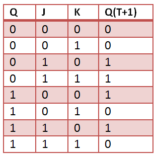
J and k are outputs a b c j k 0 0 0 0 1.
Test bench truth table.
Next we will write a testbench to test the gate that we have created.
This code will send different inputs to the code under test and get the output and displays to check the accuracy.
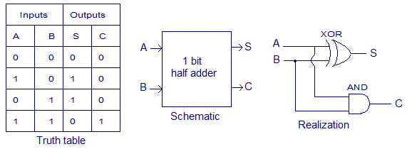
Truth table of simple combinational circuit a b and c are inputs.
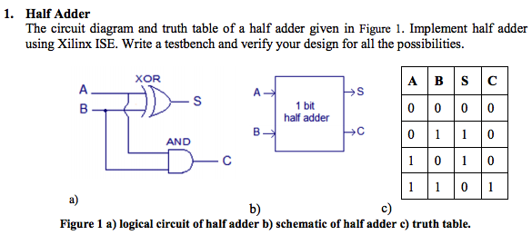
The code creates a half adder.
Am i on the right track.
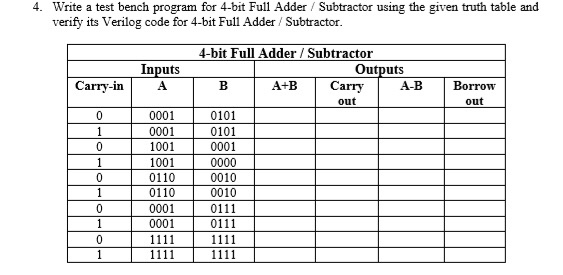
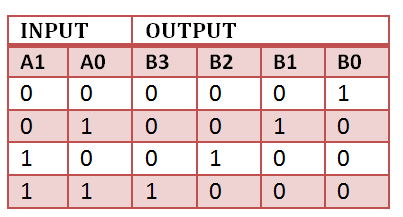
B write a vhdl module that implements the function described by the following truth table.
In this tutorial we will create a simple combinational circuit and then create a test bench test fixture to simulate and test the correct operation of the circuit.
There is also a test bench that stimulates the design and ensures that it behaves correctly.
Create a test bench and verify your implementation using simulation.
Begin p 0000 for j in 0001 to 1111 loop if j 1111 then p p 1.
A simple truth table will help us describe the design.
The test bench contains statements to apply inputs to the dut and ideally to check that the correct outputs are produced.
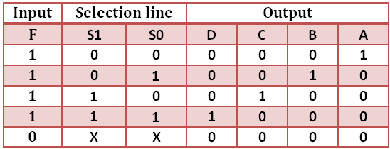
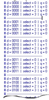
Sel 00 after 100 ns 01 after 200 ns 10 after 300 ns 11 after 400.
Wait for 5 ns.
Truth table of simple combinational circuit a b and c are inputs.
How would i do this in a vhdl test bench to run through a truth table for a multiplexer.
A single half adder has two one bit inputs a sum output and a carry out output.
A testbench is an hdl module that is used to test another module called the device under test.
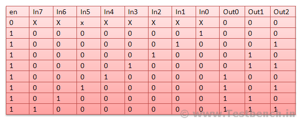
а d оооооооо oooppppoooom oooooooolo 0 нон орон орон орона h8 h h h 8 o h 8 8 6 8 8 8 8 1 1 1 1 0 1 1 1 1 1 1 1 1 1 1.
Testbench is another verilog code that creates a circuit involving the circuit to be tested.
Using vivado to create a simple test fixture in verilog in this tutorial we will create a simple combinational circuit and then create a test fixture test bench to simulate and test the correct operation of the circuit.