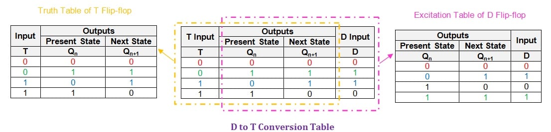
Truth table characteristic table and excitation table for t flip flop contribute.
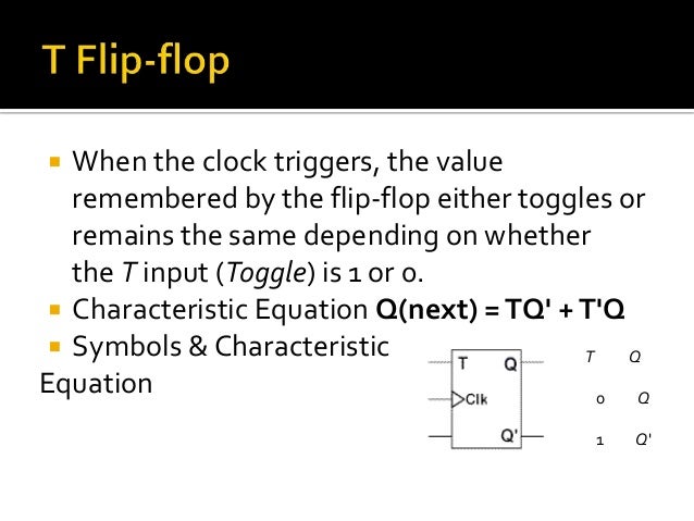
T flip flop characteristic table.
Digital flip flops are memory devices used for storing binary data in sequential logic circuits latches are level sensitive and flip flops are edge sensitive.
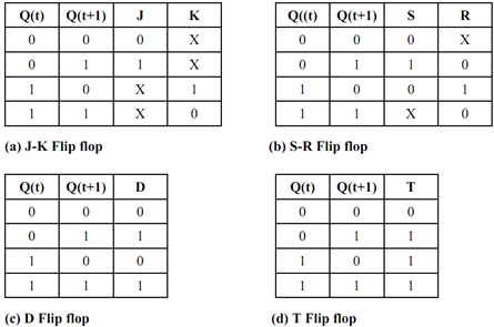
Truth tables characteristic equations and excitation tables of different flipflops nand and nor gate using cmos technology circuit design of a 4 bit binary counter using d flip flops.
It means that the latch s output change with a change in input levels and the flip flop s output only change when there is an edge of controlling signal that control signal is known as a clock signal q.
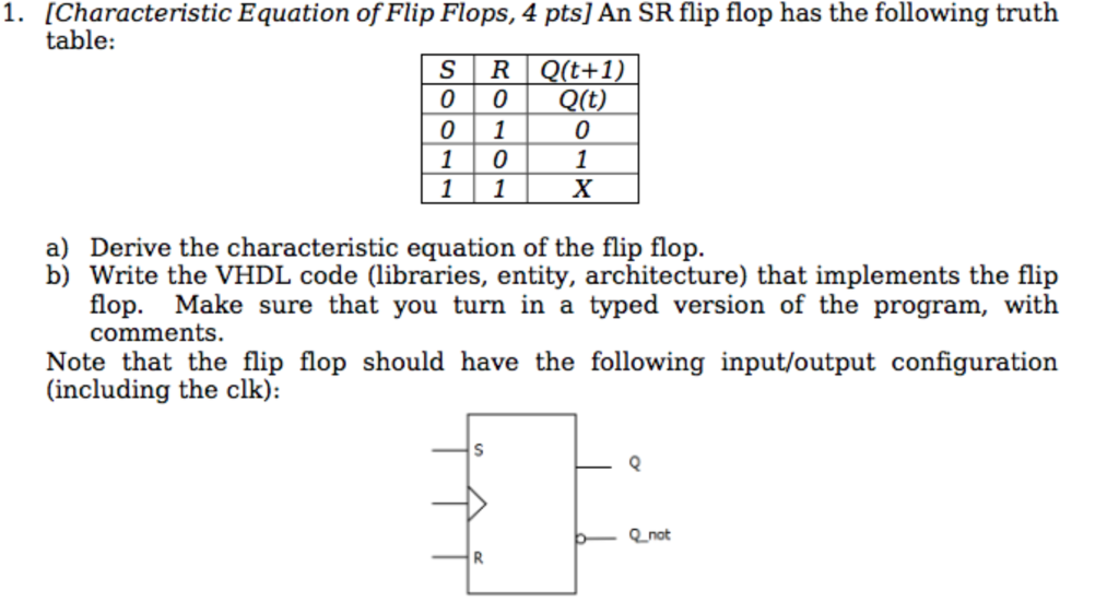
The truth table of a t flip flop is shown below.
If the output q 0 then the upper nand is in enable state and lower nand gate is in disable condition.
For example consider a t flip flop made of nand sr latch as shown below.
Here in this article we will discuss about t flip flop.
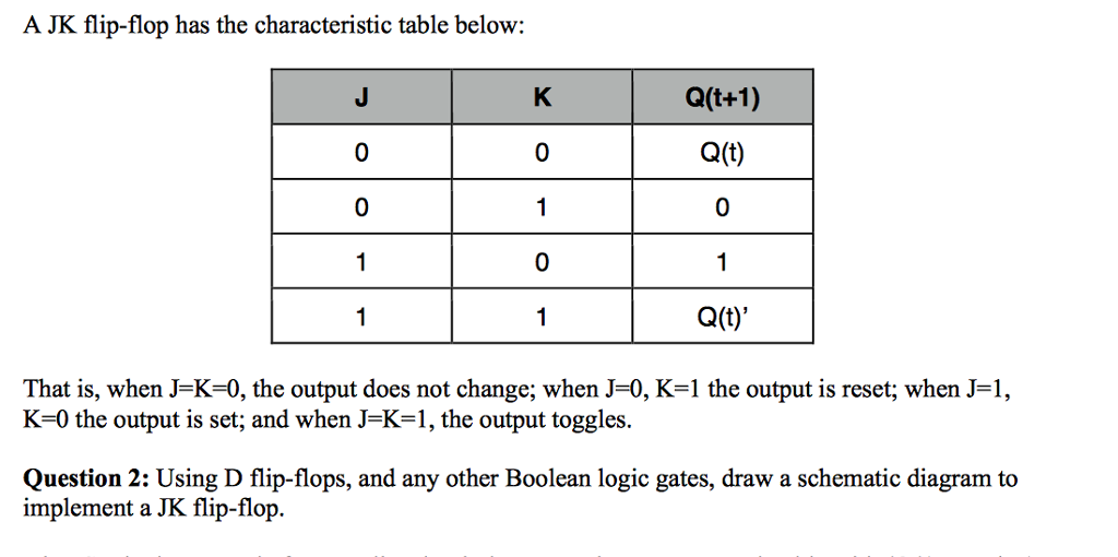
These are basically a single input version of jk flip flop.
Therefore consider the characteristic table of d flip flop and write down the excitation values of t flip flop for each combination of present state and next state values.
It operates with only positive clock transitions or negative clock transitions.
In this article let s learn about different types of flip flops used in digital electronics.
T flip flop is the simplified version of jk flip flop.
This flip flop has only one input along with the clock input.
Jk flip flop jack kilby t flip flop toggle out of the above types only jk and d flip flops are available in the integrated ic form and also used widely in most of the applications.
This modified form of jk flip flop is obtained by connecting both inputs j and k together.
As mentioned earlier t flip flop is an edge triggered device.
It is obtained by connecting the same input t to both inputs of jk flip flop.
The circuit diagram of t flip flop is shown in the following figure.
A t flip flop is like jk flip flop.
Truth table of t flip flop.
The name t flip flop is termed from the nature of toggling operation.
The characteristic table is useful during the analysis of sequential circuits when the value of flip flop inputs are known and we want to find the value of the flip flop output q after the rising edge of the clock signal.
The next state for the t flip flop is the same as the present state q if t 0 and complemented if t 1.