15 19 14 3 20 1 3 alarm signal 2 aux.
System sensor 2351e smoke detector wiring diagram.
A copy of this list is available from system sensor upon request.
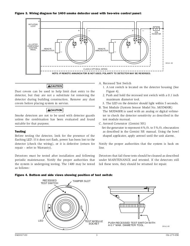
Wiring diagram 2w b and 2wt b 2 wire zone 2 wire control panel 2w b or 2wt b 5 ra 4 ra 3.
This chart contains the current list of detectors and ul listed compatible control units.
Nfpa standards 72 and 90a should also be refer enced for detailed information.
2351e system sensor europe manualzz installation and maintenance instructions for model low smoke detector स टम सर c o n v e t i a l b401 products wiring diagram melder magazines lst user s manual sv 7299 conventional spot type bases 2351e system sensor europe manualzz installation and maintenance instructions for model 2351e low installation and maintenance read more.
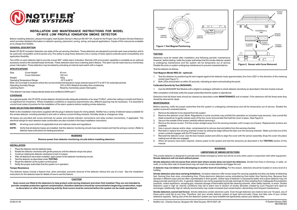
Test the detector as follows.
Wiring guide system wiring diagram for 4 wire duct smoke detectors wiring diagram for dh100acdclp to ssk451.
System sensor europe 3 horsham gates horsham west sussex rh13 5pj united kingdom tel.
Wiring diagrams figure 3a.
A hardwired smoke alarm installation involves wiring one of the smoke detectors closest to the voltage source to a 120 vac breaker in the main electric panel or tapping from a 120 v electrical box wiring it using a 14 2 cable with a black live a white neutral and a ground wire as shown by the diagram in figure 5.
Assortment of duct smoke detector wiring diagram.
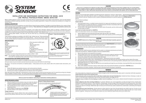
Read system sensor s applications guide for duct smoke detectors hvag53 which provides information on detector spacing placement zoning wiring and special applications.
Conventional optical smoke detector automatic drift compensation voltage 8 30vdc current 0 16ma quiescent and 80ma in alarm ip43 when installed on wb 1 shroud 30 to 70 c certificate 0832 cpd 0059 ademco 2610ec.
System sensor smoke detector wiring diagram a novice s guide to circuit diagrams.
It reveals the elements of the circuit as streamlined shapes and also the power and also signal connections between the devices.
A wiring diagram is a simplified traditional photographic depiction of an electric circuit.
39 040 9490 111 fax.
Wiring diagram shown is for dh100acdclp 4 wire duct smoke detector system equipped without a control panel.
As identified by system sensor s compatibility chart.
Conventional optical smoke detector.